MPO 카세트 극성 설명: A형 / AF형 / B1형 / B2형 / U형
Sep 24, 2026MPO-LC 데이터 센터 케이블링에서 카세트 극성은 MPO 트렁크 포트와 전면 LC 듀플렉스 포트 간의 광섬유 매핑을 설정합니다. 이는 송신 경로와 수신 경로가 일치하는지 여부를 결정하며, 이를 잘못 설정하면 링크가 아예 연결되지 않습니다. A, AF, B1, B2, U 등 5가지 주류 극성이 있으며, 각각 서로 다른 ANSI/TIA-568 케이블링 방식에 해당합니다.
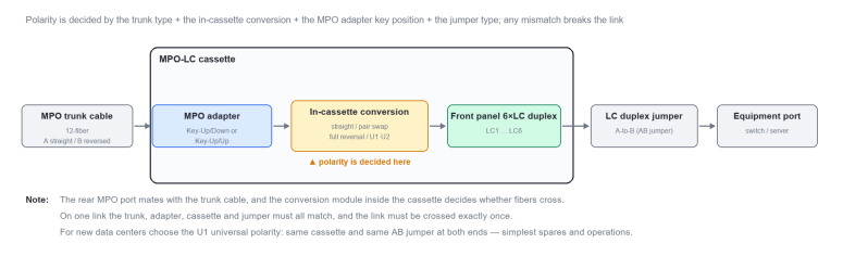
그림 1 MPO-LC 카세트: 내부 구조 및 극성이 설정되는 위치
Type-A는 Method-A를 따르며, A타입(Key-Up/Down) 어댑터를 A타입 스트레이트 트렁크와 페어링합니다. 광섬유가 카세트를 곧바로 통과하므로 1–12 시퀀스가 유지됩니다. 배치는 간단하지만 양쪽 끝에 서로 다른 점퍼(한쪽은 AA, 다른쪽은 AB)가 필요하므로 유지보수가 번거롭습니다. 주로 레거시 10G/25G 듀플렉스 LC 설치 환경에서 발견됩니다.
Type-AF도 A타입 어댑터와 A타입 트렁크를 사용합니다. 차이점은 카세트가 내부에서 쌍 교환(1↔️2, 3↔️4)을 수행하여 각 듀플렉스 포트에서 Tx/Rx를 교환한다는 것입니다. Type-A와 한 쌍으로 사용되며, 양쪽 끝 모두 AB 점퍼를 사용할 수 있게 하여 현장 패칭을 단순화합니다. 고밀도 MPO-LC 개보수에 적합합니다.
Type-B1 및 B2는 Method-B를 따르며, 둘 다 B타입(Key-Up/Up) 어댑터를 B타입 리버스드 트렁크와 함께 사용합니다. B1은 카세트 내부에 스트레이트 방식으로 되어 있어 Tx/Rx 플립이 어댑터에 의해 수행되며, 가장 흔한 B타입 극성입니다. B2는 카세트 내부에서 전체 1–12 시퀀스를 반전시키므로 플립이 카세트 자체에서 처리되며 스트레이트 트렁크와 페어링되어야 합니다(리버스드 트렁크를 사용하면 두 번 반전되어 링크가 끊어짐). B2는 일반적으로 호환성이 떨어지는 공급업체별 설계입니다. 두 가지를 절대 혼용하지 마십시오.
Type-U(U1/U2)는 ANSI/TIA-568.3-E(2022)에서 추가된 범용 극성이며 신규 구축 시 선호되는 선택입니다. U1과 U2 모두 B타입 트렁크와 AB 듀플렉스 점퍼를 사용하며, 양쪽 끝 모두 동일한 U타입 카세트를 사용할 수 있어 카세트 타입을 구분할 필요가 없습니다. 차이점은 어댑터에 있습니다. U1은 A타입 어댑터를 사용하여 멀티모드와 싱글모드를 모두 지원하며 모듈 브레이크아웃/집성에 주로 사용됩니다. U2는 B타입 어댑터를 사용하며 주로 멀티모드 듀플렉스 채널에 사용됩니다. 이들의 부품은 상호 호환되지 않습니다.
표 1 6가지 카세트 극성 유형별 빠른 선택 가이드
|
극성 |
케이블링 방식 |
MPO 어댑터 |
트렁크 케이블 |
카세트 내 매핑 |
듀플렉스 점퍼 |
일반적인 용도 |
|
Type-A |
Method-A |
A타입 Key-Up/Down |
A타입 스트레이트 |
스트레이트스루 |
한쪽은 AA; 다른쪽은 AB |
레거시 10G/25G 듀플렉스 |
|
Type-AF |
Method-A |
A타입 Key-Up/Down |
A타입 스트레이트 |
쌍 교환(1↔️2, 3↔️4) |
양쪽 모두 AB |
고밀도 MPO-LC 개보수 |
|
Type-B1 |
Method-B |
B타입 Key-Up/Up |
B타입 리버스드 |
스트레이트스루 |
양쪽 모두 AB |
가장 흔한 B타입 극성 |
|
Type-B2 |
Method-B |
B타입 Key-Up/Up |
A타입 스트레이트 |
전체 반전(1↔️12) |
AB 양끝 |
제조사 전용 디자인 |
|
Type-U1 |
Method-U1 |
A타입 Key-Up/Down |
B타입 반전 |
U1 변환 |
AB 양끝 |
멀티모드 + 싱글모드 브레이크아웃 |
|
Type-U2 |
Method-U2 |
B타입 Key-Up/Up |
B타입 반전 |
U2 변환 |
양쪽 끝 AB |
다모드 듀플렉스 채널 |
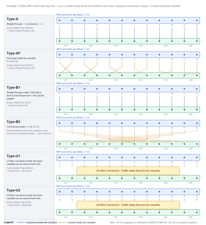
그림 2 6가지 극성 유형의 카세트 내 광섬유 매핑 (12심 MPO → 6×LC 듀플렉스)
엔지니어링 규칙: 링크당 하나의 극성 시스템을 유지하십시오. 시스템 간에 A/AF, B1/B2 또는 U를 절대 혼용하지 마십시오. 신규 데이터 센터의 경우 U1을 선호하고, 레거시 개보수의 경우 필요에 따라 A/AF 또는 B1을 맞추십시오.
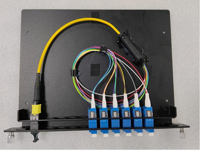
그림 3 현장의 MPO-LC 카세트: 후면의 12심 MPO, 전면의 6개 LC 듀플렉스 포트로 팬아웃됨
자주 묻는 질문 (FAQ)
Q1 카세트가 사용하는 극성을 어떻게 신속하게 식별합니까?
MPO 어댑터 키 위치로 시작하십시오. Key-Up/Down(A형)은 대개 A, AF 또는 U1을 의미하고, Key-Up/Up(B형)은 대개 B1, B2 또는 U2를 의미합니다. 그런 다음 카세트 라벨과 트렁크 케이블이 스트레이트 스루인지 리버스인지 확인하십시오. 카세트가 내부적으로 광섬유를 교차하는지 여부는 외부에서 볼 수 없으므로, 공급업체의 광섬유 매핑 테이블로 확인하고, 중요 링크의 경우 가시광선원으로 코어마다 검증하십시오.
Q2 A형과 AF형은 둘 다 A 방식인데, 왜 반드시 쌍으로 사용해야 합니까?
A형 카세트에서는 광섬유가 그대로 통과하고 Tx/Rx 교차가 점퍼에 의해 이루어집니다. 반면 AF형은 그 교차를 카세트 내부로 이동시킵니다. 함께 사용하면 링크의 양쪽 끝에서 AA형이 필요한지 추적할 필요 없이 둘 다 AB 점퍼를 사용할 수 있습니다. 전체 링크가 A형만 또는 AF형만 사용하는 경우, 교차가 한 번 부족하거나 한 번 너무 많아져 결국 Tx/Rx가 교차된 상태로 끝납니다.
Q3 신규 데이터 센터에 U1형이 권장되는 이유는 무엇입니까?
U1/U2를 사용하면 양쪽 끝이 동일한 카세트와 동일한 AB 점퍼를 사용하므로 “A단 카세트”와 “B단 카세트”의 구분이 없습니다. 예비 부품이 하나만 필요하므로 확장 및 장애 교체가 최대한 간단해집니다. U1은 A형 어댑터를 사용하며 멀티모드와 싱글모드를 모두 지원합니다. U1과 U2는 서로 다른 어댑터를 사용하며 부품이 호환되지 않으므로 하나의 링크에 혼용하지 마십시오.
Q4 극성이 잘못되면 어떻게 되며, 어떻게 문제 해결을 합니까?
일반적으로 양쪽 끝의 트랜시버가 링크를 설정할 수 없기 때문에 링크가 활성화되지 않거나 패킷이 자주 손실됩니다. 다음 순서로 문제를 해결하십시오. (1) 양쪽 끝의 카세트 극성 유형이 실제로 일치하는지 확인합니다. (2) 트렁크 케이블이 스트레이트 스루인지 리버스인지 확인합니다. (3) 점퍼가 AA인지 AB인지, 그리고 양쪽 끝이 일관성이 있는지 확인합니다. (4) 가시광선원이나 광파워 미터를 사용하여 코어별로 매핑을 검증한 다음, 결함이 있는 코어 위치가 파악되면 해당 부품을 교체합니다.

주소 : Room 901, Building 6, JD Smart Industrial Park, No. 128, Juhua Stone Avenue, Huashan Town, Huadu District, Guangzhou City
전화 : +86 15989256178
Whatsapp : +86 15914235380
이메일 : sales@fiberwdm.com